Build the RV Link Hardware
This guide covers the complete bill of materials (BOM), step-by-step assembly, and best practices for wiring the RV Link unit into your coach's RV-C CAN network.
Bill of Materials (BOM)
The following components are recommended for a reliable and high-performance RV Link unit. Equivalent parts may be substituted, but ensure they meet the required specifications.
Core Components
- Compute: Raspberry Pi 5 (4GB recommended)
- CAN Interface: Waveshare 2-CH CAN HAT Plus
- Storage Adapter: Waveshare M.2 NVMe HAT+ Cooler
- Storage: NVMe SSD (128GB or larger recommended)
Cabling & Enclosure
- CAN Cable: Shielded twisted pair cable (22-24 AWG)
- RV-C Tap: 3M Mini-Clamp Connector or equivalent T-connector
- Enclosure: Official Raspberry Pi 5 Case (or custom 3D printed)
- Power: Official Raspberry Pi 27W USB-C Power Supply
- Mounting: DIN rail clips, VHB tape, or mounting screws as needed
Supplier links are for reference only. Prices and availability may vary. Using an NVMe SSD is highly recommended over a microSD card for long-term reliability.
Wiring the RV-C CAN Network
Properly connecting to the RV-C bus is critical for reliable operation. The RV-C network is a two-wire bus carrying CAN_H (High) and CAN_L (Low) signals.
Key Principles
- Protocol: RV-C is based on the J1939 standard, using 29-bit identifiers at a 250 kbit/s bitrate.
- Twisted Pair: Always use a twisted pair of wires for the CAN_H and CAN_L signals to reduce electrical noise.
- Termination: The CAN bus must have exactly two 120Ω termination resistors—one at each physical end of the main bus trunk. Do not add a third terminator.
- Polarity: CAN_H on the RV Link HAT must connect to CAN_H on the coach bus. CAN_L must connect to CAN_L. Reversed polarity will prevent communication.
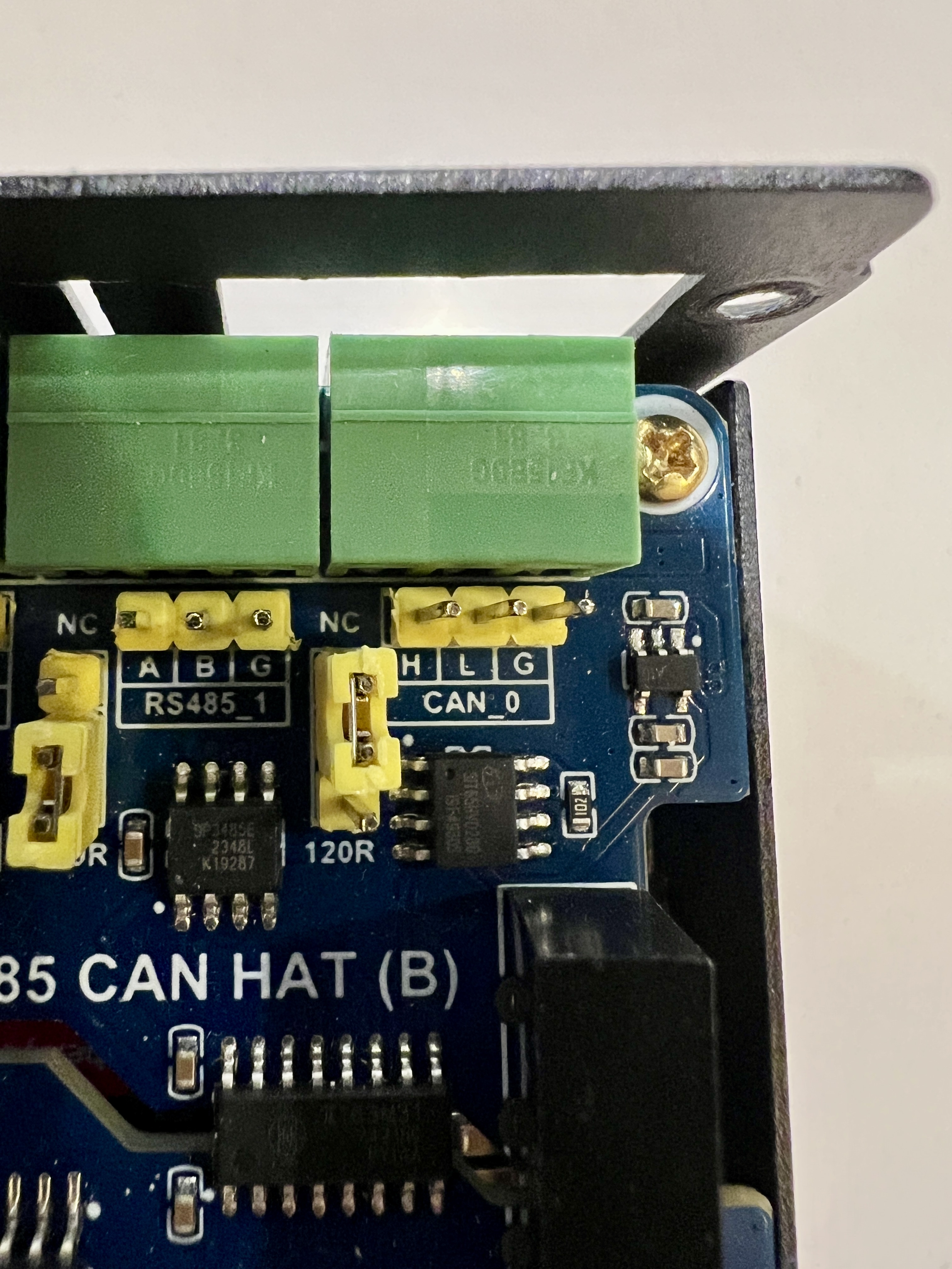
HAT Connection
- Channel: Use the screw terminals for CAN Channel 1 (CH1) on the Waveshare HAT.
- Connections: Connect your twisted pair to the `CAN1_H` and `CAN1_L` terminals.
- Termination Jumper: Ensure the 120Ω termination jumper on the HAT is OFF unless your RV Link unit is at one of the physical ends of the bus.
- Keep Leads Short: Keep the "stub" or "tap" wire from the main bus to your device as short as possible (ideally under 1 meter).
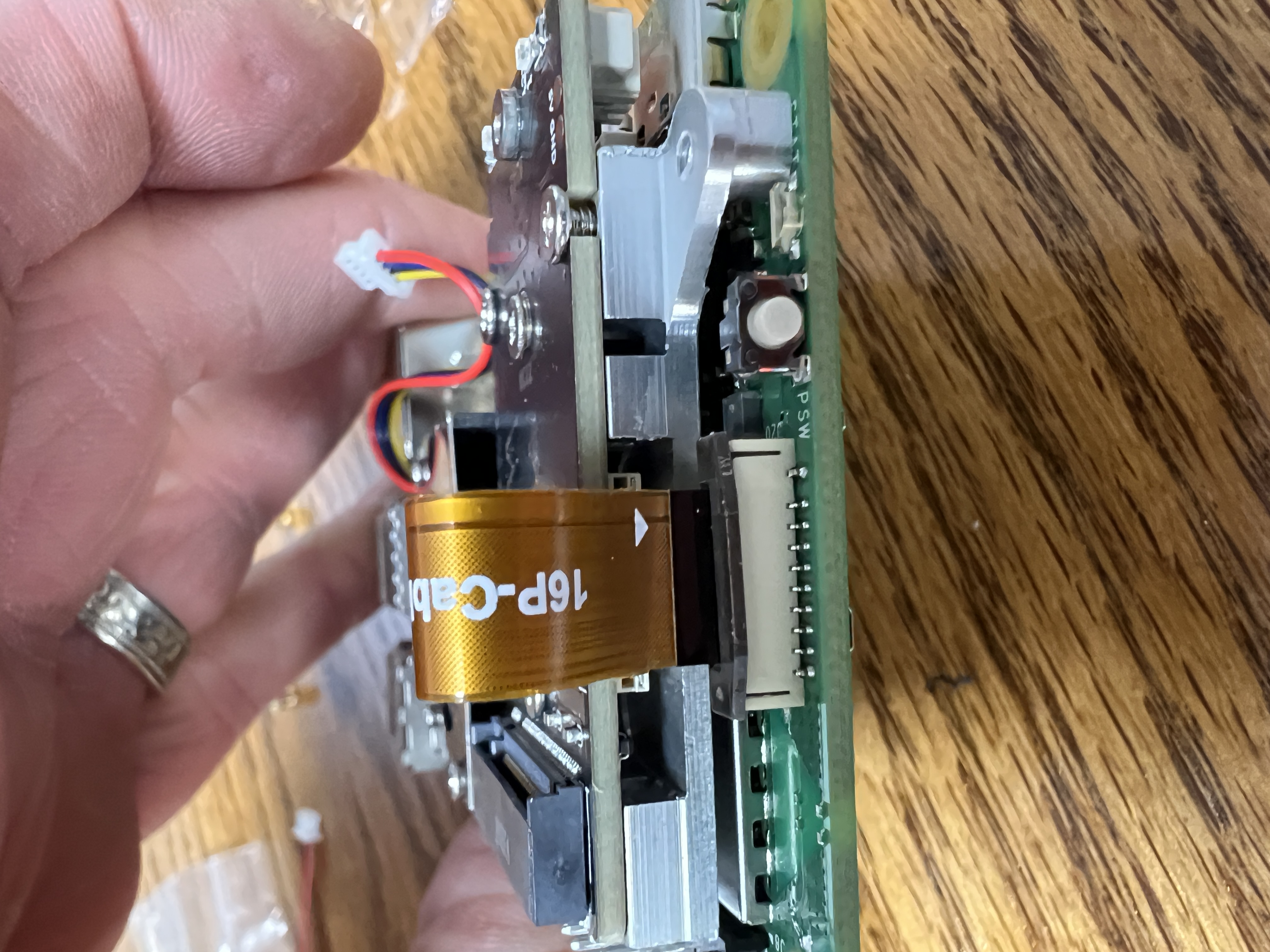
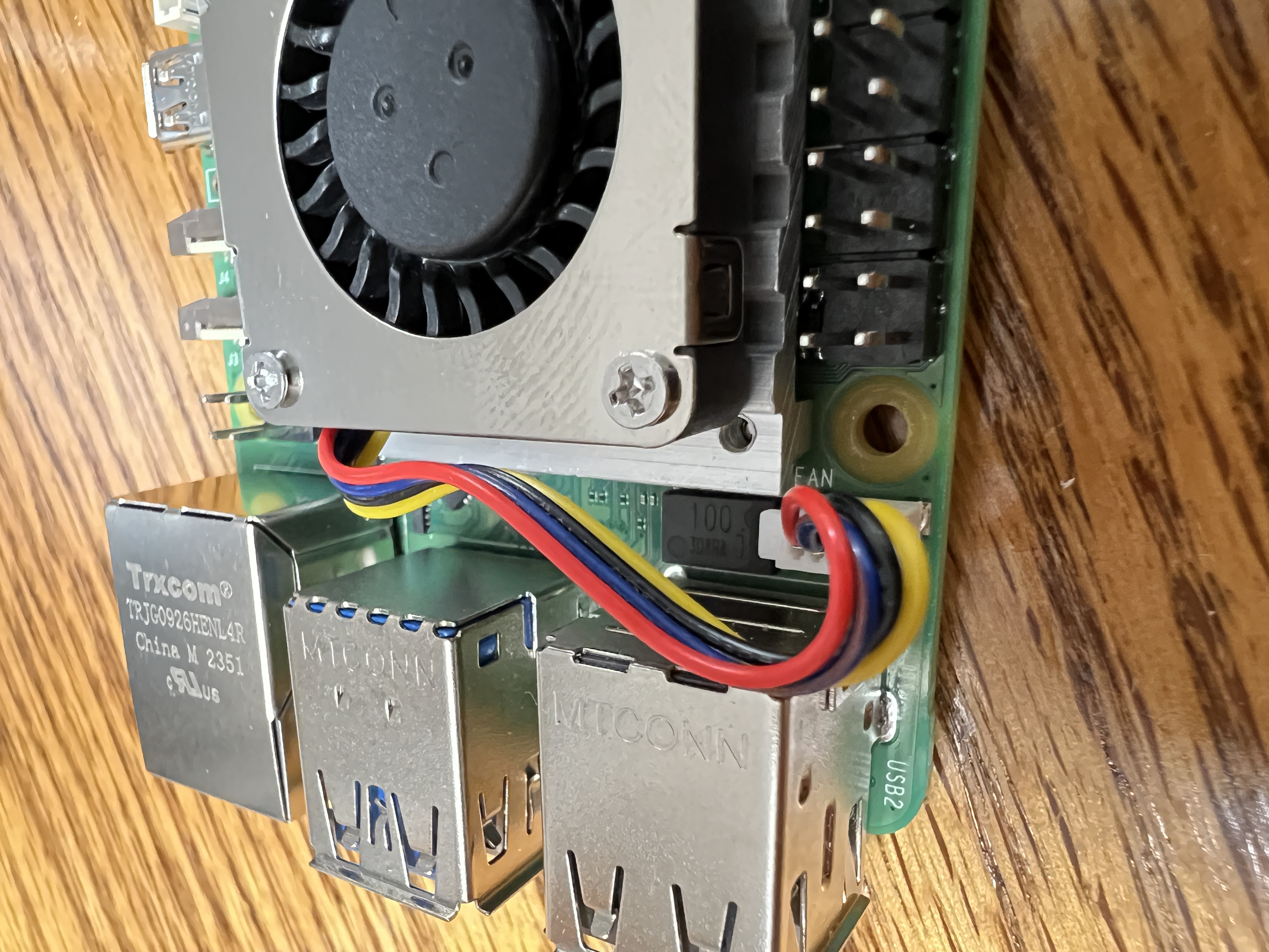
Assembly Steps
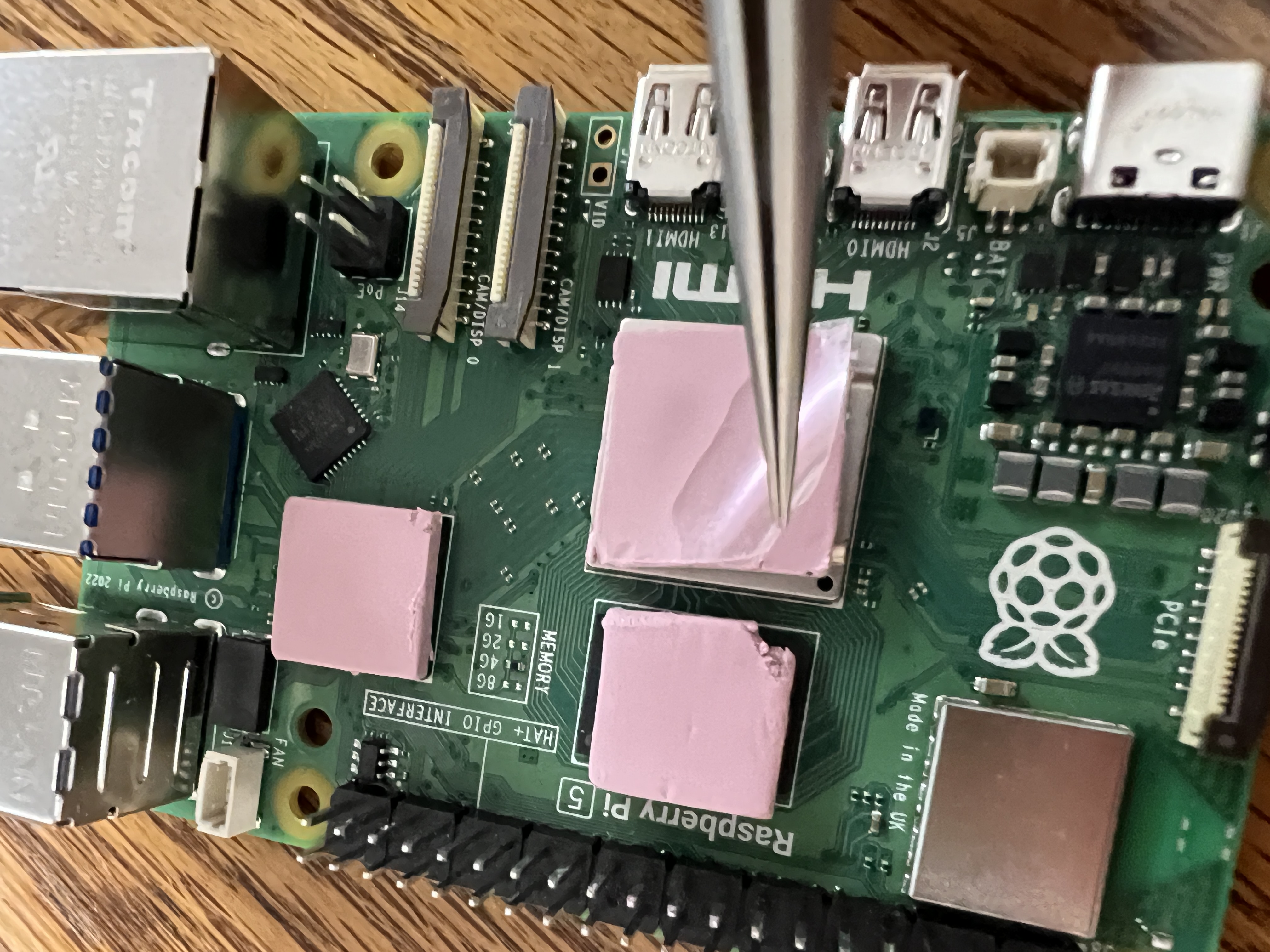
- Prepare the Pi: Install the M.2 NVMe carrier onto the Raspberry Pi 5. Insert the NVMe SSD and attach the active cooler.
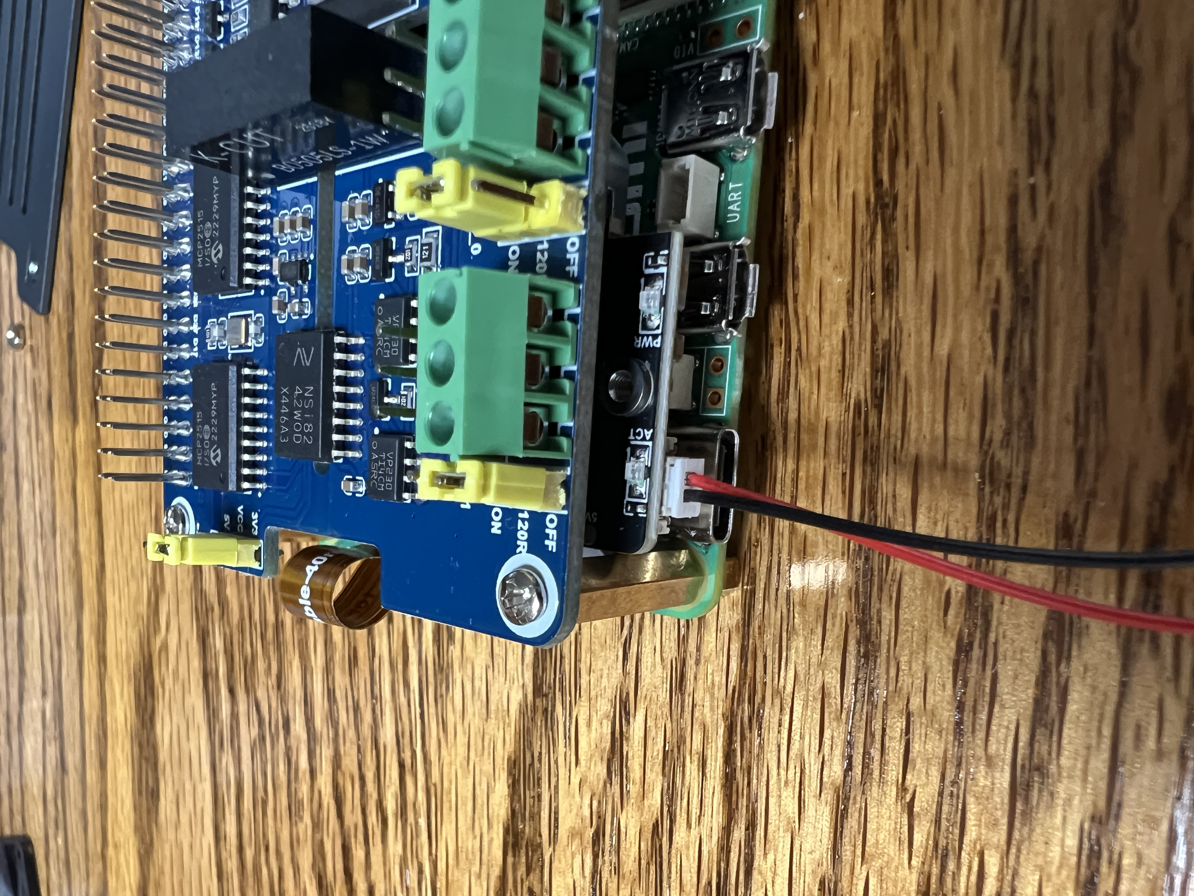
- Mount the CAN HAT: Securely mount the Waveshare 2-CH CAN HAT on top of the Pi's GPIO pins, using the included standoffs to ensure a stable connection.
- Enclose the Unit: Place the assembled stack into your chosen case. Ensure the case allows for adequate airflow for the cooler.
- Prepare the CAN Cable: Strip and terminate your twisted pair CAN cable, ready for connection to the HAT's screw terminals.
- Final Connections: Connect the CAN_H and CAN_L wires to the HAT. Do not apply power yet.
- Bench Test: Before installing in the coach, power the system on your workbench. Follow the Software Guide to install the OS and add-ons, and verify that the CAN interface is detected.
Assembly Photos
Placeholder: Replace these images with a step-by-step gallery showing the assembly process.
In-Coach Installation
Power Source
Provide a clean and stable power source. Using the official Raspberry Pi power supply connected to a 120V outlet is ideal. If tapping into the coach's 12V system, use a high-quality DC-to-DC converter rated for the Pi 5's power requirements.
Mounting Location
Choose a location that is dry, protected from extreme temperatures, and allows for airflow. Secure the unit firmly to prevent vibration damage. Ensure the location is accessible for future maintenance.
Pre-Flight Checklist
- All HATs and boards are securely seated with standoffs.
- CAN_H and CAN_L polarity is correct and connections are tight.
- The CAN bus has exactly two 120Ω terminators (and the HAT jumper is likely OFF).
- The power supply is stable and meets the Raspberry Pi 5's requirements.
- The unit is securely mounted and protected from the elements.